Abstract
The patented Selman Non-Motorized Gas Trap is an innovative device designed to enhance the accuracy and efficiency of gas extraction and analysis in mudlogging operations. By leveraging a non-mechanical, passive design, this gas trap minimizes maintenance requirements, eliminates reliance on electrical power or compressed air, and provides a robust solution for challenging wellsite environments. This paper explores the design principles, operational mechanics, advantages, and applications of the Selman Non-Motorized Gas Trap in the oil and gas industry.
1. Introduction
Gas traps are critical components of mudlogging operations and wellsite geological analysis, enabling the extraction and measurement of hydrocarbon gases dissolved in drilling fluid (mud). Traditional motorized gas traps often face challenges such as power dependency, mechanical failure, and maintenance issues in harsh environments.
The Selman Non-Motorized Gas Trap addresses these challenges by offering a passive, robust, and efficient design. This innovation not only improves reliability but also reduces operational costs and environmental impact.
2. Design Principles
The Selman Non-Motorized Gas Trap is engineered to use the natural flow of drilling fluid to facilitate gas extraction. Key design elements include:
2.1 The Rig is the Agitator
As drilling fluids are circulated, fluid travels from the bit at the bottom of the hole back to the surface through the annulus. As this fluid returns to the mud system, it spills over into the flow line, creating a natural turbulence and churning effect.
This turbulence of drilling fluid spilling into the f low line naturally liberates hydrocarbon gasses to the top (non-liquid section) of the flow line much in the same way an agitator would stir the drilling f luid in the “possum belly” of a shale shaker.
2.2 Gas Sampling at the First Source
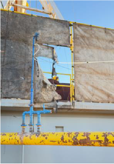
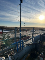
The Selman Non-Motorized Gas Trap is normally installed on the flow line just after the Blowout Preventer (BOP) so that it can take advantage of sampling gas as soon as possible after the natural rig agitation occurs. The trap is placed on top of the natural “flash point” where the most gasses are liberated, and suction is applied to the top of the trap so that a representative sample of gasses can be collected as the drilling fluid and liberated gasses pass by.
Therefore, gases are collected before they travel further downstream to the shale shakers and the rest of the closed loop mud system. This positioning eliminates the tendency to measure as many recycled and contamination gasses, instead predominantly measuring liberated or produced gasses.
2.3 Compact and Durable Construction
Made from heavy duty steel and other ruggedized materials, the trap is designed to withstand the hazardous, harsh, and abusive environments that are present on oil and gas drilling locations. From explosive or poisonous gas environments to abrasive and corrosive chemicals present in drilling fluids, this trap stands the test of time in its ability to continue operation with minimal maintenance.
2.4 Gas Capture for Any Configuration
The device is designed to optimize efficient gas capture regardless of whether the drilling rig is configured to drill with air, water-based mud (WBM), or oil-based mud (OBM) including synthetic oil-based mud.
The Selman Non-Motorized Gas Trap is also designed to prevent fluid incursion into the gas sample line. If for some reason, fluid in the flow line is 100% full underneath the trap, the ever present suction will be broken automatically via the vacuum relieve valve. If for some reason a “surge” of drilling fluid occurs, pushing drilling fluid into the trap and possibly the gas sample line, the gas sample line can be purged of drilling fluid from a safe distance with an optional “blow back” industrial automation system that can be controlled remotely.
This system monitors pressures and can divert flows of compressed air back toward the trap, clearing the line. Afterwards, gas capture and measurement can resume. Normally, this optional functionality is only available on our remotely-monitored gas logging platform, the WITSender. Without it, the gas sample line can be manually purged by personnel on location.
3. Operational Mechanics
3.1 Installation
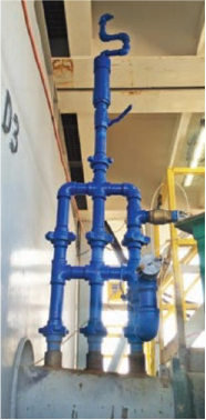
Installation Location: The Selman Non-Motorized Gas Trap is easily installed on the mud flow line ideally just after the Blowout Preventer (BOP). Its compact design allows for quick deployment without significant modifications to existing systems.
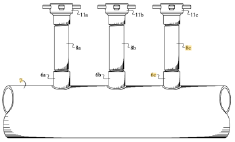
Three 2” couplings need to be welded to the appropriate place near the top of the flow line with the trap present, and that’s it! This installation only needs to be performed one time for each rig, then we’re good to go for the foreseeable future.
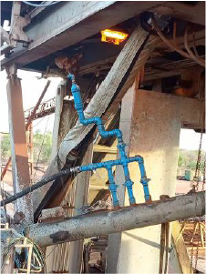
Alternate Installation Locations: In cases where the flow line is non-weldable (i.e. if the flow line from the moving BOP down to the stationary shale shaker area is made of rubber), our second choice for trap installation is on the first weldable accessible area on the flow line BEFORE the shakers. This secondary installation location still measures gas appropriately; however, it comes with new challenges that may need to be addressed.
3.2 Removal
The trap is easy to remove for a switch of drilling contractor, rig move or laying down of rig. We simply remove our trap at the hammer unions, unscrew our pipe adapters from the welded couplers, then plug each of the three 2” couplers with steel plugs.
3.3 Gas Extraction
Drilling Fluid Flow: Drilling fluid spills from the annulus into the flow line, and those flow dynamics create a turbulence zone which liberates the hydrocarbon gases entrained in the drilling fluids.
Gas Capture: Liberated gases are collected in the inside chamber of the trap and directed to gas analysis equipment via the sampling line. The gas sampling line and inner trap gas collection chamber are under a weak vacuum under normal operating conditions. This weak vacuum provides the means for the gas sample to travel back to the gas analysis equipment.
Fluid Avoidance: The trap has been specially designed to avoid fluid incursion either in the trap itself or the gas sample line. We make use of hydrostatic fluid properties and multiple travel paths to passively avoid fluid incursion. Some attached optional systems may also actively remediate fluid incursion.
3.4 Integration
The gas trap works with many common industry-used gas flow and conditioning systems which prepare the gas sample for introduction to total hydrocarbon analyzers (THAs), Gas Chromatographs (GCs), and other analytical gas measurement or detection equipment. This compatibility ensures seamless integration into mudlogging workflows.
4. Advantages of the Selman Non-Motorized Gas Trap
4.1 Reliability
No Moving Parts: Eliminates mechanical wear and reduces the risk of failure.
Power Independence: Operates without electrical power, making it ideal for remote or power constrained locations.
4.2 Efficiency
Optimized Gas Extraction: High-efficiency design ensures maximum gas liberation, even in low-flow or low-gas scenarios.
Consistent Performance: Maintains reliability under varying drilling conditions, including those where traditional agitators cannot be placed or where traditional 4 agitators cannot measure gas. Examples include newer rigs with closed off or otherwise blocked “possum bellies” on shale shakers, drilling with air, or the inability to constantly maintain a traditional agitator if not on location.
4.3 Cost Effectiveness
Low Maintenance: Minimal maintenance requirements reduce downtime and operating costs.
Longevity: Durable materials and design ensure a long service life.
4.4 Environmental Benefits
Reduced Waste: Passive operation minimizes energy consumption and associated emissions.
Safe Operation: Eliminates the risk of mechanical failure leading to fluid spills or gas leaks.
5. Applications
The Selman Non-Motorized Gas Trap is suitable for a wide range of drilling environments and operations, including:
5.1 Exploration & Production Drilling
Provides accurate gas data critical for formation evaluation in exploratory wells. With today’s varying drilling fluid compositions and a need to quickly reconfigure systems while batch drilling many wells on a drilling location, the Selman Non-Motorized Gas Trap alleviates issues while reconfiguring mud systems or switching to other wells on the same pad (“skidding”).
No reconfiguration or adjustment of the trap is necessary while performing these rig adjustments. On most rigs, in the primary installation position (especially if the shale shakers are on the moving part of the rig), the gas sample tubing will need to expand and contract to adjust to the new rig distance on each borehole However, if the shale shakers are on the stationary part of a rig that does not move between boreholes, the secondary installation position may be more desirable since neither the trap nor the gas sample tubing would need to move with the rig between boreholes.
5.2 Remote Operations
Ideal for remote locations where power sources are limited, unreliable, or in hard-to-reach places. Power sources, in the form of electricity or compressed air can sometimes be challenging to tap at a drilling location.
While a compressed air source or electrical outlet may be located in close proximity to a traditional agitator location, depending on the rig, there may be a high level of competition for those outlets. Compressed air fittings may have to be changed or branched into multiple outlets, and special explosion-proof electrical outlets may not be the same or compatible across all rigs, leaving our personnel to work with rig contractor personnel frequently at the start of and sometimes during the drilling activities to accommodate are need for electrical or compressed air power.
With the electrical power and / or compressed air needs met in a more standard area such as “trailer row” or near the VFD / SER equipment, any electrical and/or compressed air needs are more easily met for other parts of our system that require it.
5.3 Harsh Environments
Performs reliably and safely in oil and gas field harsh environments. Since the areas in which all hydrocarbon gas traps reside are by their very nature harsh and hazardous, any safety and reliability improvements that are made will add to the overall safety and efficiency of the entire drilling rig.
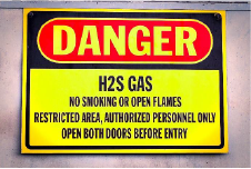
Oil and gas drilling locations present several hazards including: high temperatures, high pressures, corrosive or abrasive fluids, potentially explosive levels of hydrocarbon gasses, potentially toxic or fatal levels of poisonous gasses, and the potential for personnel to come into adverse contact with extremely heavy equipment or vehicles. The more that we can do to mitigate the need for personnel to enter this harsh environment, the better. Since the gas trap has no moving parts, no need to be powered, and no need to be oiled or maintained up close the personnel safety exposure is minimized.
6. Field Case Studies
6.1 Remote Permian Wells
The Selman Non-Motorized Gas Trap has been employed on hundreds of Permian Basin remotely monitored, gas-logged wells over the past several years. It continues to be employed today. In these conditions, we have no personnel on location full-time to maintain the trap or the rest of the system. The device has performed and continues to perform very reliably throughout all these wells, providing consistent gas data.
Using our remotely monitored gas logging units, we can monitor the entire system remotely and get alarms when exceptional circumstances occur. Most times we succeed in correcting any issues that arise remotely. If an issue cannot be resolved remotely, technicians are available to correct issues with the system, however, issues with the gas trap are rare indeed.
6.2 Manned Permian Wells
In multiple Permian Basin wells, we have performed traditional agitator vs non-motorized gas trap studies. When comparing the gas readings between the two trap types, they have many similarities when comparing gas composition and relative increases and decreases of value. The non-motorized gas trap is distinct, though, in that the magnitude of the gas peaks is frequently higher than a traditional agitator, and the gas peaks seemed to be sharper and higher resolution versus depth.
These two distinctions most likely occur due to the gas sampling location. The non-motorized gas trap acquires hydrocarbon gasses at the “flash point” just beyond the BOP or before the shale shakers while the traditional agitator is normally located in the “possum belly” of a shale shaker. The “flash point” contains more raw, higher concentrations of gas (especially while drilling with a rotating head). Gas is liberated as the rig circulates / drills. On the other hand, the “possum belly” tends to get more “averaged out” gas readings. While the “possum belly” gets fresh drilling fluid 7 while the rig is circulating, we could still be measuring gas entrained in the stagnant drilling fluid inside the “possum belly” when the rig is not circulating / drilling, causing less sharp gas resolution.
6.3 Western Australian Manned Wells
The Western Australian Basin study was performed in conjunction with an international oil and gas services company. In this case, a traditional gas trap and the Selman non-motorized gas trap were setup and employed simultaneously. Hydrocarbon gasses from each were measured simultaneously using two separate instrument clusters (each with a total hydrocarbon analyzer and gas chromatograph) and two separate sample f low and conditioning systems.
Gas analysis instrumentation and sample f low systems were different than the systems that we normally employed. Nonetheless, the non-motorized gas trap performed admirably when compared with the traditional gas trap equipment.
The results of this study were very similar to the “Manned Permian Wells” study, except the results were even closer this time because the service company was employing a traditional heated-probe circulation and extraction gas trap. These results help underline the fact that the Selman Non-Motorized gas trap may be used in a variety of locations, with a diversity of gas sample flow and conditioning systems, and a plethora of gas measurement instrumentation.
7. Challenges
7.1 Challenges
Custom Installation: Some drilling setups may require minor modifications for optimal performance.
Initial Training: Operators may need brief training to understand the passive mechanics of the system.
8. Conclusion
The patented Selman Non-Motorized Gas Trap represents a significant advancement in mudlogging technology. Its innovative design addresses the limitations of traditional motorized gas traps, offering a reliable, efficient, and cost-effective solution for gas extraction in drilling operations. By reducing power dependency, maintenance needs, and environmental impact, the Selman Gas Trap sets a new standard for the industry.
References
- Selman et al. “System for Sampling Fluid from a Well with a Gas Trap”, US Patent 7,844,400 B1, November 30, 2010
- Selman et al. “Gas Trap for Sampling Fluid from a Well”, US Patent 7,957,903 B1, June 7, 2011
- Selman et al. “Method for Sampling Fluid from a Well with a Gas Trap”, US Patent 8,132,452 B1, March 13, 2012